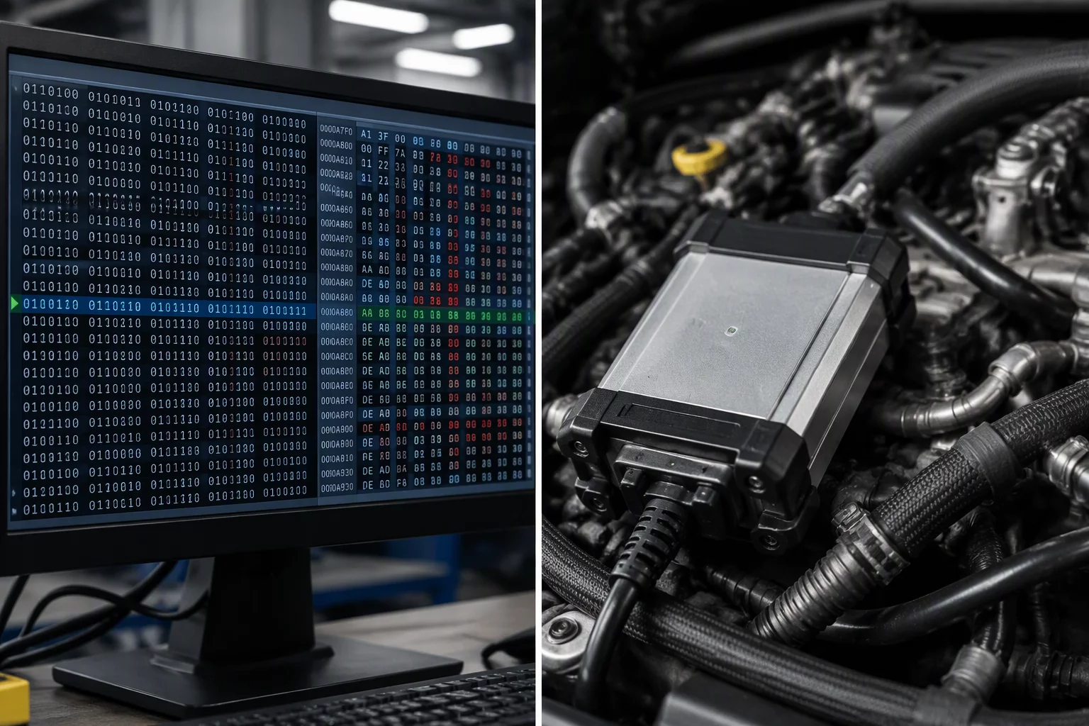
The Structural Blindspot of Static Differential Analysis
When engineers inspect two binary calibration roms using differential tools like Beyond Compare or VCM Editor Compare, the visual feedback is reassuringly concrete. Cell coordinates highlight in bold colors, showing exactly where scalar constants or two-dimensional maps deviate from the baseline dump. This level of inspection confirms syntactic changes between two files, satisfying basic revision tracking requirements.
However, confusing a clean static comparison with system validation creates significant operational liabilities. Binary compare utilities only inspect static data at rest; they possess no insight into the internal execution threads, scheduling loops, or table arbitration hierarchies within the powertrain control module. A table modified by two percent might calculate correctly inside the editor, yet cause unintended multiplier compounding during transient spark retard calculations.
Establish Standardized Baseline Ledgers
Review our documented change protocols for separating byte verification from empirical runtime validation.
Three Dimensions Where Static Comparison Fails Functional Integrity
Static file comparison operates in an isolated environment devoid of physical reality. To validate a calibration revision properly, three critical operational dimensions must be evaluated across dynamic test cycles:
- Sensor Transfer Dynamics: Static maps do not account for physical sensor latency, voltage ripple, or intake charge temperature soak across repeated pulls.
- Cross-Table Multipliers: Complex ECU architectures stack transient correction, atmospheric compensation, and torque intervention tables simultaneously, creating emergent behaviors hidden from simple 2D view.
- Hardware Degradation & Drift: Injector flow disparities, fuel pump voltage sag, and mechanical wastegate spring tension changes produce vastly different operational outputs from the exact same calibration file.
Engineers must therefore treat file comparison as merely step one in a rigorous two-step verification workflow. The differential file establishes what the calibration intended to alter, while recorded high-frequency CAN bus telemetry proves whether the powertrain controller responded within defined safety boundaries.
“File comparison tells you what was written to the flash ROM; functional validation proves whether the engine survived the commanded calculation under full thermal load.”
Building an Audit-Proof Ledger Workflow
An audit-ready calibration ledger requires closing the loop between binary diffs and logged execution proofs. Each committed calibration entry should link the exact hexadecimal delta hash directly to a timestamped diagnostic scan record containing wideband lambda, ignition advance, intake manifold pressure, and knock retard data points.
When field issues occur or subsequent calibrators review past revisions, this dual-layered documentation eliminates guesswork. Instead of wondering why a specific timing map was altered by 1.5 degrees, the auditing team can instantly verify the accompanying log files showing how knock sensor thresholds responded during that precise dyno run.