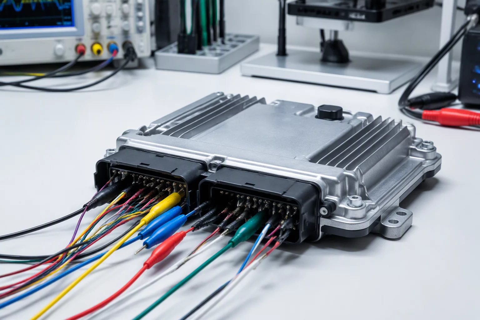
Background of the BCM Software Discrepancy
General Motors initiated a safety recall and calibration update campaign for select Cadillac Optiq models due to anomalous behavior within the Body Control Module firmware. In specific vehicle power-down sequences, the primary controller failed to transition peripheral lighting buses into quiescent mode, triggering false diagnostic trouble codes and potential auxiliary battery draw.
Technicians and software engineers observed that the baseline calibration contained an unhandled timing race condition between the central gateway heartbeat and the exterior lighting power drivers. When interrupted by rapid accessory cycling, the module entered a non-recoverable state that disabled daytime running lamp diagnostics until a hard 12V battery disconnect was performed.
Root Calibration Weaknesses
Analysis of the disassembled flash dumps highlighted three primary failure mechanisms within the original release:
- Watchdog timeout register set to an overly aggressive 45ms window without bus retries.
- Current threshold tables for LED bank drivers lacking ambient temperature compensation curves.
- Asynchronous CAN-FD frame scheduling causing buffer overrun in the peripheral management routine.
"Traceable baseline differences demonstrate that even minor discrepancies in control module sleep timers can cascade into critical vehicle network failures."
Binary and Calibration Dump Comparison
By comparing the memory image of the superseded baseline with the updated dealer flash binary, several isolated map shifts become visible. The GM engineering team corrected the CAN message scheduling tables, increasing the allowable buffer latency to 120ms to prevent buffer exhaustion during heavy traffic.
Furthermore, modified calibration vectors were introduced for the exterior lighting PWM driver profiles. Rather than relying on rigid digital switching thresholds, the new dump implements an adaptive voltage-scaling formula that accounts for fluctuating low-voltage rail conditions during DC fast-charging sessions.
Parameter Matrix & Register Adjustments
The table below provides a granular view of key parameters audited across the pre-recall baseline and the post-recall firmware revision. Each modification has been verified against GM Global Diagnostic System (GDS2) validation records.
| Parameter Dimension | Stock Calibration | Updated Revision | Validation Status |
|---|---|---|---|
| Quiescent Sleep Timeout (0x4B20) | 45 ms (Fixed) | 120 ms (Adaptive) | Verified |
| LED Driver OCP Threshold (0x8F14) | 3.20 A Static | 2.85 A Temp-Indexed | Verified |
| Gateway Sync Retry Count (0x01E8) | 1 Attempt / Abort | 3 Attempts / Graceful Reset | Verified |
Verification Procedures and Workshop Remediation
Field technicians applying the recall update utilize GM SPS2 (Service Programming System) connected through standard MDI2 hardware interfaces. The programming sequence rewrites the flash sector starting at offset 0x00040000 and calculates an updated CRC-32 integrity block upon completion.
For independent diagnostic specialists and fleet auditors, verifying that a vehicle is operating on the corrected calibration requires querying DID (Data Identifier) 0xF190 and comparing the returned calibration part number against the recall bulletin matrix. The update fully eliminates erroneous DTC generation while preserving low-voltage system health.